Week of 12/8 - 12/12
- kaurmanji0719
- Dec 11, 2025
- 2 min read
This week, I continued to work on fixing the issue with the PCB for the Word Clock. Most of the week was filled with investigating and testing different elements of the PCB to spot where exactly it wasn't working. Last week, I fixed the issue of the header connection by resoldering the connection between the clock and the PCB. This did not resolve the issue. Since the old PCB we were comparing it to was working for some of last week, I thought the issue might be the capacitor on the PCB that was messing with the clock, because we took off the capacitor from the old board to use it on the new one.
To test this theory, I moved all the elements to a breadboard. By doing this, I would be able to easily remove and add elements to the breadboard to sus out the issue. Initially, when I connected the capacitor to the breadboard, it didn't light up the board. But after about 2 minutes, it lit up. Usually, the delay for the clock turning on is not that long, so I found it odd that it actually ended up turning on past the minute-long delay it follows.

After finding that the capacitor still lights up the board, I moved to testing out different-sized capacitors. The PCB was using a 35V 1000 microfarad capacitor. So in place of this one, I tried one that was 25V 1000 microfarad and another that was 50V 470 microfarad. With all of these capacitors, the board lit up. This made it clear to me that the capacitor was not the issue with the PCB, so it had to be somewhere else on the board. I attempted to use a smaller capacitor on the PCB just to see how it would impact the clock's functionality, but I accidentally broke the traces while soldering it to the board.


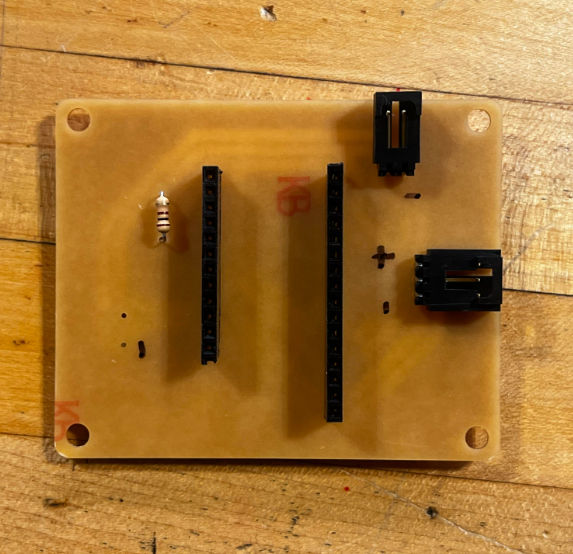
The only next step I'm left with now is remilling a PCB and being a little bit more careful with connecting the elements once the board is soldered. Other than that, the things I tested told me all my elements were correct, and it was the actual board that I have to deal with to get this clock working properly. So far, I've milled the PCB, and now I just have to solder everything to it and test it with the board and power supply.


Comments