Week of 12/1-12/4
- kaurmanji0719
- Dec 4, 2025
- 2 min read
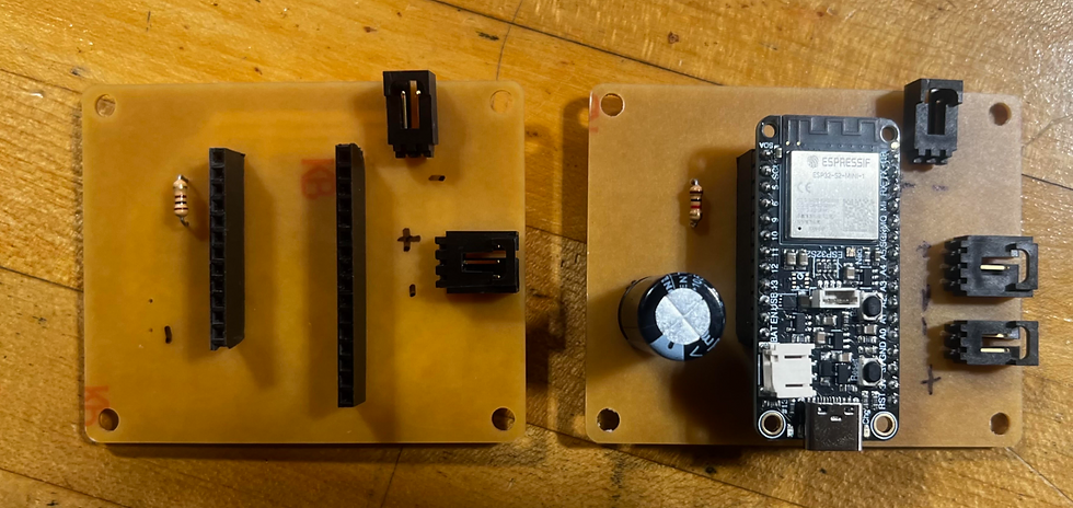
This week I continued working on the Word Clock PCB. Last time I was here I got the PCB milled and soldered. On Tuesday, I checked all the connections across the back of the PCB to ensure the traces were properly connected to the elements I soldered. The connections were solid and properly connected, so I proceeded to try it out on the Word Clock itself.
When we connected the new PCB to the Word Clock, we found that it did not light up the board. When it was positioned exactly correctly, a few lights would turn on then immediately turn back off. We tried it again and it didn't work. We tried to find the reason for why it wasn't working but had no success in finding the issue. We then went back to the old PCB we had made to see what the differences between the two. the only thing that differed from the first PCB to the most recent one is that it had another connection to circulate the power and we removed the capacitor from the 1st one to add it to the most recent one. The older PCB worked fine when we connected it to the Word Clock, aside from the fact that it did not circulate power to the bottom of the board because it didn't have the second connection to power.
We found that even though the older PCB worked, the connection was finnicky, making the clock turn off and on randomly if the PCB moved only a little bit. We played around with some of the wires and found that the headers that connected the board to the PCB might have been the issue. I cut the heat shrink off of the connection we made for the wires and found that one of the wires had disconnected or broken.


I resoldered all of the connections for the wires just to ensure they were all working properly when we tested it again. After I did this, I reconnected the old board with the new header and found that it still did not power the board properly. Because of this, I checked the connections on the PCB to see where exactly the board was not connecting to power. I found that the power connection itself was not receiving any power, this could be because the pad might have come up when we plugged the power wires in and pulled them out often as we had been doing.


After discussing it with Mr. Christy, I decided to move away from the old PCB and focus fully on just trying to get the new PCB to work, seeing as it has all the elements we actually need, unlike the previous one which is missing some important connections. Before, we noticed that some of the traces had buckled during our testing, which could mean that we have to design a PCB with larger traces that can support the current that needs to flow to the board. The connections on this new PCB are all still solid, so changing the traces might be what we have to do next to get this board to work. Next week, I hope to get the PCB running properly.


Comments